With the timing chain, gears and cover all removed (see previous posts) removing the cam shaft is very simple. Just undo the thrust washer and it’ll slide out (carefully).
…
First is to flip the engine upside down and remove the oil pump and pan.
Showing the crankshaft and piston connecting rod ends…
It may be needed to rotate the crankshaft until a piston connecting rod end in accessible and also in line with the piston.
1 – The piston rod bolts undone. 2 – The bearing cap gently knocked free. 3 – The bearing cap removed.…
To remove the crankshaft pulley and timing chain cover…
To remove the pulley is simple. It’s held on by 6 bolts to the harmonic balancer. It may be necessary to slide something (screwdriver etc) through an access hole to stop the pulley from rotating.
Now to remove the harmonic balancer. A screwdriver through a hole will stop it from rotating. A large bar on the end of the…
First remove the valve covers.
Then the valley cover.
Now remove the rocker arm assemblies, these are held on by a nut. Now the push rod can be pulled out. Be sure to organise where eveything came from, so if need be it can go back in the same place. I used cardboard, polystyrene and bags and numbered everything.
Now the valve lifters can be removed by…
The engine in it’s very own, new, home:
1 – the intake manifold. 2 – all the manifold bolts removed, I didn’t follow a sequence for undoing them just dotted about loosening each one gradually. 3 – hard to see but there was a bolt that is screwed into the manifold with a nut holding it to the timing chain cover. This would not play nice, so I had to chop…
The driveshaft universal joint to be removed. This doesn’t rotate smoothly – it’s very clunky – so a new one will be installed after the shaft is painted.
First step is to remove the retaining C-clips. Any tool with a point will do for this.
Now the u-joint will be able to move (forcibly, not freely) for the next step. Put a socket larger than the u-joint bearing…
The traction arm aka radius rod aka torque arm aka whatever else…
Pressure wouldn’t budge these bushings so the alternative was this. The traction arm front bushing being burned out with a weed burning torch.
I burned the rear one out as I wasn’t sure how the new ‘Ultimate Performance High Technology Polygraphite’ (overkill compared to all my other rubbers, but it’s all I could find) bushings would…
Somehow I missed this earlier. Had to remove the rest of the ball joint from the lower control arm. Thankfully it was easy to do.
This is the thing to remove:
Just hit it with a hammer around the edges…
…until it starts to break free…
…then hit it some more until it’s completely out.
Some cleaning to do then it’s ready for a new…
(Removing bushing sleeves from lower control arm.) Didn’t know for certain that the new lower control arm bushings would include the outer metal sleeves. But they do:
So, had to remove all of the ones I left in previously, in case I didn’t get new ones.
Simply used a chisel, hammer and brute force…
… and lots of WD40…
… to eventually get them all out.…
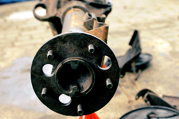
This is the rear brake assembly mounted to the rear axle.
To remove the backing plate the whole axle shaft needs to be removed. Begin by dismantling the old brakes. See here for a detailed step-by-step process.
Once the brakes are off, you can get to 4 mounting bolts holding the backing plate to the axle – through the access hole in the wheel rotor.
Don’t forget…
 ;)

 ;)
 ;)
 ;)
 ;)
 ;)
 ;)
 ;)
 ;)
 ;)
 ;)